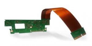
Rigid Flex Circuits
Rigid flex circuits allow engineers to incorporate the functionality of multiple rigid PCB layers into a single, thinner, more flexible laminate. They can reduce product weight, size and assembly time. They can also improve reliability and performance. They can also absorb shock, vibration and temperature fluctuations, reducing stress on the copper conductors, solder joints, and other components in the finished product.
However, it is important to understand that not all electrical and electronic companies can design, manufacture and assemble rigid-flex printed circuits for specific applications. To ensure the best quality and cost-to-performance ratio, it is recommended to select a turnkey manufacturer that can offer all these services at a single location. This also helps to avoid multivendor miscommunication and errors that can increase the time-to-market and cost of your project.
rigid flex circuits boards can be manufactured from a variety of materials, including FR4 (insulation), RT/FT-flex (conductive silver or copper) and others, depending on the application. They are generally fabricated using the same processes as rigid PCBs, except the conductors are plated on both sides.
Can Rigid Flex Circuits Be Customized For Specific Applications?
During the design phase, it is important to take into account that a rigid-flex board can be folded and twisted during fabrication. This is especially important for dynamic flex circuits, where the copper conductors can fracture during bending. For this reason, it is recommended to orient the flex regions so that they lie along the grain of the material.
It is also a good idea to limit the number of flex circuit elbows or large open sections during the design phase. These types of structures are more likely to fail during reflow assembly because they will not be properly supported by the rigid panel sections. In addition, they may not have enough structural integrity to withstand the heat of the reflow oven.
Using the same layer-stack as a rigid PCB, a flex circuit will be etched on both sides and cut to the appropriate shape before it can be used in a final assembly. The exposed copper surface will then be chemically plated with tin and/or soft gold to provide protection and improve abrasion resistance.
The etching process is typically performed by immersing the lamination in an etchant solution, or by spraying an etching agent onto the mask patterns. Once the etching is complete, the plated copper conductors are then transferred to the flex circuit using a copper deposition process, similar to that used for rigid PCBs. Finally, the flex circuit is laminated to a rigid-powder core to complete the assembly.